- Home
- Products
- Solutions
- About Sinolink


HuaDong&HuaBei District
HuaDong&HuaBei District
XiNan&XiBei District
XiNan&XiBei District
Other
Other


SFDC-A Series Multi-Octave Downconverter belongs to our microwave downconverter series that has a high performance and an octave overage by RF signal. Its frequency step is precise and accurate to 10Hz with a variety of IF and signal bandwidth choices. This series of converter is mainly used for electronic countermeasure system, radar system, and satellite communication system. Its excellent phase noise, clutter suppression, and in-band flatness data can provide a transparent RF transmission channel to all videos or data communications. All programming commands can be set through a local panel or through network remotely. SFDC-A Series Microwave Downconverter is available in 2U/4U sizes.
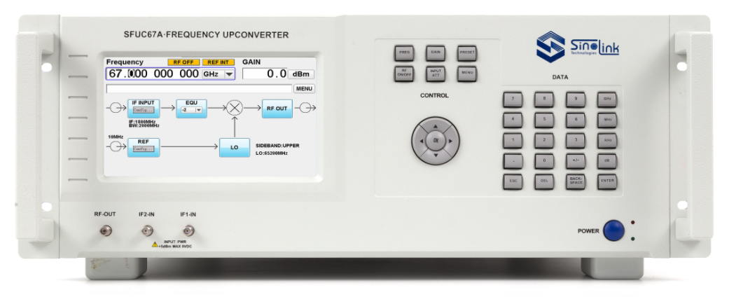
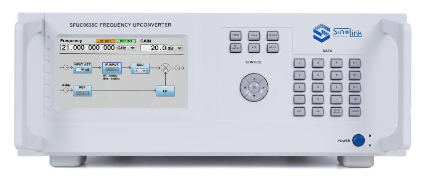
SFUC-A Series Multi-Octave Downconverter belongs to our microwave downconverter series that has a high performance and an octave overage by RF signal. Its frequency step is precise and accurate to 10Hz with a variety of IF and signal bandwidth choices. This series of converter is mainly used for electronic countermeasure system, and communication system. Its excellent phase noise, clutter suppression, and in-band flatness data can provide a transparent RF transmission channel to all videos or data communications. All programming commands can be set through a local panel or through network remotely. SPUC-A Series Microwave Downconverter is available in both 2U and 4U sizes.
|
Specifications of SFDC-A Series Multi-Octave Downconverter |
||||||||
|
|
SFDC20A |
SFDC26A |
SFDC40A |
SFDC50A |
SFDC67A |
|||
|
Input Characteristics |
Frequency Range |
0.5~20GHz |
0.5~26.5GHz |
0.5~40GHz |
0.5~50GHz |
0.5~50GHz |
||
|
Frequency Tuning Step Size |
10Hz |
|||||||
|
Maximum Input of Signal Power |
-30dBm(operating) +10dBm(damaged) (+5dBm operating, ATT35 support) |
|||||||
|
Input LO Leakage |
≤-80dBm |
|||||||
|
Input VSWR |
≤2.5 |
≤2.5 |
≤2.5 |
≤2.5 |
≤2.5 |
|||
|
Input Impedance |
50Ω |
|||||||
|
Output Characteristics |
Output Frequency |
70±20MHz,140±40MHz,0.72±0.25GHz,1.2±0.25GHz,1.2±0.5GHz, 1.8±1GHz,3±2GHz(Select between single or multiple IF outputs) |
||||||
|
P-1 Output Power |
≥+13dBm |
|||||||
|
IM3 Output |
≤-60dBc (△5MHz, Maximum gain, Power output:2*-10dBm) |
|||||||
|
Output Impedance |
50Ω |
|||||||
|
Output VSWR |
≤1.4 |
|||||||
|
Transfer Characteristics |
Gain |
10~45dB |
||||||
|
Tunning Step Size |
0.1dB |
|||||||
|
Gain Resolution |
≤±1dB |
|||||||
|
Level Stability |
≤±0.5dB/day at room temperature |
|||||||
|
Gain Flatness/Signal Bandwidth |
≤±0.3dB/40MHz, ≤±0.5dB/80MHz, ≤±1dB/500MHz, ≤±1.5dB/1000MHz, ≤±2dB/2000MHz, ≤±3dB/4000MHz, ≤±2dB/Full Band |
|||||||
|
IF Inband Frequency Clutter/Signal Related |
<-55dBc (0dBm output, excluding IF output harmonics) |
|||||||
|
IF Shutdown Feature |
≥80dB |
|||||||
|
Noise Figure (Maximum Gain) |
≤12dB |
≤15dB |
≤18dB |
≤18dB |
≤20dB |
|||
|
Image Rejection |
≤-60dBc |
|||||||
|
Phase Noise (dBc/Hz) |
≤-50@10Hz |
≤-50@10Hz |
≤-50@10Hz |
≤-50@10Hz |
≤-50@10Hz |
|||
|
≤-80@100Hz |
≤-80@100Hz |
≤-75@100Hz |
≤-75@100Hz |
≤-75@100Hz |
||||
|
≤-95@1kHz |
≤-95@1kHz |
≤-95@1kHz |
≤-95@1kHz |
≤-95@1kHz |
||||
|
≤-102@10kHz |
≤-102@10kHz |
≤-100@10kHz |
≤-100@10kHz |
≤-100@10kHz |
||||
|
≤-102@100kHz |
≤-102@100kHz |
≤-100@100kHz |
≤-100@100kHz |
≤-100@100kHz |
||||
|
≤-108@1MHz |
≤-108@1MHz |
≤-105 @1MHz |
≤-105 @1MHz |
≤-105 @1MHz |
||||
|
Reference Characteristics |
Internal Reference Frequency Stablity |
±2e-8 (0℃~+50℃, after 30min power on) |
||||||
|
Internal Reference Frequency Accuracy |
0.05ppm |
|||||||
|
Internal Reference Power Output |
5±2dBm,50Ω,10MHz,Sine wave |
|||||||
|
External Reference Power Input |
5±2dBm,50Ω,10MHz,Sine wave |
|||||||
|
Reference Phase Noise |
≤-125dBc/Hz@10Hz |
|||||||
|
≤-140dBc/Hz@100Hz |
||||||||
|
≤-150dBc/Hz@1kHz |
||||||||
|
≤-155dBc/Hz@10kHz |
||||||||
|
≤-155dBc/Hz@100kHz |
||||||||
|
Physical Characteristics |
RF Input Ports |
2.92mm-K |
2.92mm-K |
2.92mm-K |
2.4mm-K |
1.85mm-K |
||
|
Other Output And Input Ports |
IF Output: SMA-K |
|||||||
|
I/Q Output: SMA-K |
||||||||
|
External Reference Input: SMA-K |
||||||||
|
Internal Reference Output: SMA-K |
||||||||
|
Control Interface |
RJ-45(TCP/IP over Ethernet )/RS422 |
|||||||
|
Power Supply |
AC,176~264VAC,45Hz~65Hz,Power consumption 140W |
|||||||
|
Overall Dimensions /Weight |
SFDC20A is 2U:483mm*90mm*550mm 15kg |
|||||||
|
SFDC26A/SFDC40A/SFDC50A/SFDC67A are 4U:483mm*178mm*582mm 25kg |
||||||||
|
Environment |
Operating |
Temperature: 0℃~+50℃ |
||||||
|
Humidty: Up to 95% @30°C, Noncondensing |
||||||||
|
Height: 3000 meters |
||||||||
|
Nonoperating |
Temperature: -30℃~+70℃ |
|||||||
|
Humidty: Up to 95% @40°C, Noncondesing |
||||||||
|
Height: 12000 meters |
||||||||
|
Shock and Vibration: Regular road transport/air transport |
||||||||
|
Options of SFDC-A Series Multi-Octave Downconverter |
||
|
Name |
Model |
Description |
|
RF Input Range |
SFDC20A |
RF Input 0.5-20GHz |
|
SFDC26A |
RF Input 0.5-26.5GHz |
|
|
SFDC40A |
RF Input 0.5-40GHz |
|
|
SFDC50A |
RF Input 0.5-50GHz |
|
|
SFDC67A |
RF Input 0.5-67GHz |
|
|
IF/BW IF/Bandwidth |
SFDC-MA |
IF Output 70±20MHz |
|
SFDC-MB |
IF Output 140±40MHz |
|
|
SFDC-MC |
IF Output 0.72±0.25GHz |
|
|
SFDC-MD |
IF Output 1.2±0.25GHz |
|
|
SFDC-ME |
IF Output 1.2±0.5GHz |
|
|
SFDC-MF |
IF Output 1.8±1GHz |
|
|
SFDC-MG |
IF Output 3±2GHz |
|
|
IQ Baseband Input |
SFDC-IQ |
IQ Baseband Output |
|
ATT35 |
SFDC-ATT35 |
Maximum input of signal power increased from -30dBm to +5dBm |

 | CONNECT WITH US |